The Remote Gateway turns on
automatically after connecting the micro USB power cable into its appropriate
socket.
When turned on, the relevant LED indications on the Remoter GW will
lit based on the following LEDs indication table:
|
Seq. # |
State |
Power |
FDX |
LNK |
100M |
ACT |
|
1 |
Power Up Sequence |
On |
Off |
Off |
Off |
Blinking for ~8sec |
|
2 |
Ethernet link inactive |
On |
Off |
Off |
Off |
Off |
|
3 |
Ethernet link active |
On |
Off |
On |
Off |
Off |
|
4 |
In sync with Analyzer |
On |
On |
On |
Off |
Off |
|
5 |
Front-End (dongle/module) Transmits to Analyzer |
On |
On |
On |
Blinking |
Off |
Table 5 – Remote Gateway LEDs indication table
After the Power-Up Sequence (see Seq. #1 in the above table), the gateway will continuously look for an Ethernet link (see Seq. #2 and #3 in the above table),
Note: the following description assumes the gateway is connected to the broadband network through an Ethernet LAN cable via its RJ45 connector. In case a WiFi or cellular modem Is used for connecting the the broadband network, different steps may be required until the gateway received an IP address from the network and gets synchronized with the Perytons Protocol Analyzer.
After inserting the Ethernet cable
into the RJ45 socket the gateway will try to obtain an IP address by using DCHP
(by default DHCP is enabled but the user can also set static IP address for the
Gateway). Once an IP address is allocated successfully (see Seq. #4 in the above
table), the gateway can be accessed via a web brouser (the gateway hosts a
webserver application).
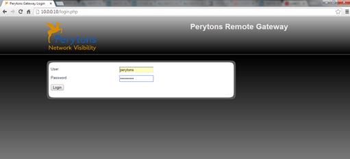
To access the gateway from a web browser, the gateway
address (IP address or IP address and port in case the gateway does not reside
in the same network) or its name; must be entered into the browser address
field:

Figure 381 – Accessing the gateway via a web brouser
Note: You can find the gateway IP address in the DHCP IP address list of your router (in case of need, you might require assistance from your IT manager to learn about your GW IP address/port). In the a.m. example the gateway IP address is 10.0.0.10.
Valid login credentials (User and Password) are needed for accessing the gateway (the default credentials are ‘perytons’ and ‘PerytonsGW’ respectively). Note that these are case sensitive.
Pressing ‘Login’ or the Enter key after valid credentials are filled, will display the gateway main configuration page (‘Home’):
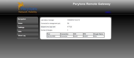
Figure 382 – Remote Gateway – main configuration ‘Home’ page
When logged in, an option to logout appears in all the gateway webpages. Pressing ‘Logout’ will revert the gateway webserver to the main ‘Home’ page and allow inserting the username and password anew:
Figure 383 – Remote Gateway – how to ‘Logout’
The gateway main page allows accessing information or setting gateway definitions by navigating into its different sections as follows:
Home page:
•Last status message – date and time of the last message transmitted from the gateway to the Perytons™ Protocol Analyzer Application
•Connected to management port status
•Elapsed since app start time – total time elapsed from the last gateway application restart – HH:MM:SS
•Number of dongles – number of dongles connected to the gateway
•Table describing information about the connected dongles:
o Port – Port type and number
o Connection - Describes connection state
o VID – Dongle Vendor Identification number
o PID – Dongle Product Identification number
o Dongle descripting name
Settings page:
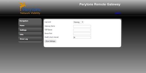
Figure 384 – Remote Gateway – ‘Settings’ page
•Log Level – This option enables to create a log file with relevant info according to the defined Log Level as follows:
o Nothing - (no log will be created)
o Critical – critical issues will be recorded to the log
o Warning – warning level issues will be recorded to the log (default level)
o Information – information level issues will be recorded to the log
o Debug – debug level issues will be recorded to the log (note that this may load the gateway and is not recommended unless guided by the Perytons support stuff)
•Gateway Name – The user can provide a freetext name to the gateway for easy recognition. When having a successful recognition of the gateway, this name will appear in the Perytons™ Protocol Analyzer capture form, next to the number of available dongles (near the gateway name in parenthesis, the number of dongles it has connected will also show):

Figure 385 – Gateway Name indication in the capture form
Note: If no dongles are connected to the Remote Gateway, the Gateway name will not be shown.
•TCP Server - In this field the user should set the IP address or domain name (e.g. 192.168.1.1 or mycompanydyndns.org – see par. 3.1), of the Perytons™ Protocol Analyzer that the gateway will be sending data to
•Server
Port- In this field the user should set the Server Port (e.g. 7452 – see par. 3.1), of the Perytons™
Protocol Analyzer that the gateway will be sending data to.
Note:
the Server Port should be the same one set in the Perytons™ Protocol
Analyzer/User Preferences/Capture TAB – ‘Remote Gateway Management TCP Port
field – see Figure
378.
If the analyzer is not located in the same network
as the gateway, and the analyzer is connected to the world through a NAT server,
this port should be defined in the NAT server (router) port forwarding table. If
the router has a uPnP option enabled the analyzer will set the port forwarding
automatically. If not, the user will need to do it manually.
•Health check interval - The Gateway initiates a Health check transmission towards the Perytons™ Protocol Analyzer according to the time interval (seconds) set in this field
After changing any of the settings on
the Settings page, the user must press  so the changes apply to the gatewaty
configuration.
After the new settings are updated a relevant notification
will appear:
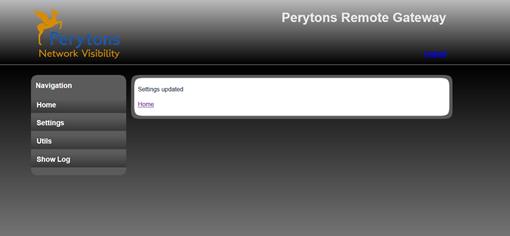
Figure 386 – Settings pae – Settings updated notification
Important Note: In order for the updated settings to take effect, the gateway application needs to be restarted – see the following paragraph (Utils page) to learn how the gateway application restart can be accomplished.
Utils page:
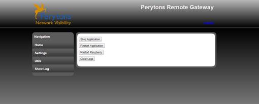
Figure 387 – Remote Gateway – ‘Utils’ page
• – Pressing the ‘Stop Application’
button causes the gateway to stop communication with the Perytons™
Protocol Analyzer
• – Pressing the ‘Restart
Application’ button causes the application that handles the sending of packets
captured by the USB dongle to the Perytons™ Protocol Analyzer to restart.
Note: If this is done during capture, the capture must be stopped, the
refresh dongles should be pressed and a new capture should start.
• – Pressing the ‘Restart Raspberry’
button causes ainitiates a boot session of the gateway hardware (and obviously
also a restar of the applications runnig on it, including the data capture and
packet transmission application).
Note: If this is done during
capture, the capture must be stopped, the refresh dongles should be pressed and
a new capture should start.
• – Pressing the ‘Clear Logs’ button
clears the content of the Log file – see following paragraph: “Show Log”
page
Show Log page:
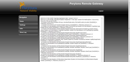
Figure 388 – Remote Gateway – ‘Show Log’ page
•Shows the log data information that the gateway collects based on the log level defined in the ‘Settings’ page (see previous relevant paragraph), This may be required by Perytons personnel when debugging issues, etc.