There are two methods for message transmission:
•One method is that the message is transmitted as close as possible to the designated time. This is based on PC time and therefore subject to PC processing latencies
•The second method is achieved when using dongles that support accurate transmission, based on dongle time stamp (such as the Telegesis - ETRX3USB 2.4GHz USB Dongle). In this mode the user provides a timestamp for every message and the message will be transmitted in this time. For this to work, there must be a queue to compensate for the PC latency, so the dongle gets the messages ~1sec before the expected transmission time and then transmits each when its transmission time occurs.
Note that the second method allows using the TG for regression test (send predefined messages with their timing and analyze the system under-test response).
The first method (together with the Scripting Add-On – see 2.8) may allow building some non-sensitive state machines (triggering message transmission according to received messages if a latency in the magnitude of 100’s of msec. is acceptable versus state machines where a very quick response after receiving a specific message is required – e.g. a very quick MAC level acknowledgment).
Notes:
a - Generating
traffic is performed by using the separate USB dongle provided along with the
Perytons™ Traffic Generator Add-On SW module (not all dongle types used by the
Perytons™ Protocol Analyzers for data capture are capable of traffic generation.
Consult the Perytons™ website or contact the Perytons Support Team – support@perytons.com
– for details).
b - If the data files that are used by the Perytons™ Traffic
Generator include different channels, this information will be reflected during
the traffic generation. This allows to easily use a single USB dongle (the
dongle controlled by the Perytons™ Traffic Generator), to transmit data in
different channels (up to 16 channels in the 2.4GHz band and 11 channels in the
SubGHz band). In parallel, a Perytons™ Protocol Analyzer relevant basic license
can be used on the same PC to capture the data from the channels
accordingly.
c - Transmission using the Perytons™ Traffic Generation tool is
done using the PC resources and depends on the PC load and resources usage at
the time of its activation. This being the situation, when using front-ends that
do not include timestamp based message transmission uncertainties of up to few
tens of msecs of when messages get actually transmitted should be expected (when
using front-ends that include timestamp based message transmission these
uncertainties are in a magnitude of µsecs.).
d – Pending PC available
resources (memory) and computing power, messages transmission rate is limited to
an average of up to 60 messages per seconds over ~1/3 of a second. Trying to
transmit messages in a higher rate might result in the delay of their
transmission.
e – Trying to transmit messages that have a time gap shorter
than 1msec between each other may introduce and additional actual transmission
delay.
d – Considering the a.m. limitations, the expected traffic generation
timing accuracy of less than ~200 µsecs., when using front-ends that include
timestamp based message transmission, or of ~10 msecs. when using other
front-ends.
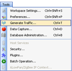
The Traffic Generation form opens when choosing 'Tools', 'Generate Traffic…':

Figure 332 – 'Generate Traffic…' in the 'Tools' menu
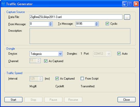
Figure 333 – 'Traffic Generator' form
Capture Source section:
•Data
File – allows choosing the capture-data file (.ANL) to use as the source for the
traffic transmission. Browsing for the chosen file can be done when clicking on
the browse icon ( )
)
•From
Message and To Message – allows choosing a range of messages to be transmitted
from the messages included in the chosen data file.
Note: The first
message number in the file is message number 0.
•Cyclic – when checked, the transmission of the messages in the 'From Message' 'To Message' fields will be performed in a cyclic mode (one cycle after the other). If unmarked, the message range selected will be transmitted only once
•Description – shows the description of the original capture data file
Dongle section:
•Device – allows choosing
the device type used to transmit the data file from a drop-down list: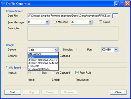
Figure 334 – 'Traffic Generator' form – choosing the device type
Note: When a dongle is recognized, the 'Dongle:' field will show the number 1, and the COM port number can be set and set using the 'Port:' drop-down list. This feature allows using a specific USB physical port for the dongle used for transmission purposes and can help if locating this dongle as separate from the receiving dongles as possible is needed (to avoid receiving unnecessary RF cross-channel interferences)
•Page - allows choosing
the page to be used from a drop-down list
Note: This option appears
only when transmitting in the Sub 1 Ghz band, i.e. a relevant Sub 1 GHz dongle
is connected and selected.
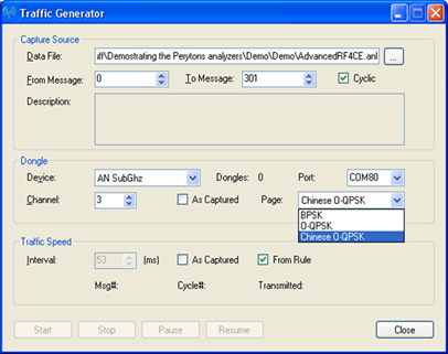
Figure 335 – 'Traffic Generator' form – choosing the SubGHz page
•Channel - allows choosing the channel to use for the traffic transmission, thus overriding the channel in which the message in the data file was actually captured
•As Captured – when marked, the transmission of the messages will follow the channel assignment on which these messages were captured in the capture file. The 'Channel' field will be discarded
•Traffic Speed section:
•Interval - allows choosing the minimal interval time to insert between transmitted messages (valid for data files that include more than a single message). This option overrides the actual time intervals between messages included in the actual data file selected
•As Captured – when marked the time between messages will follow, as close
as possible, the actual time intervals between messages as recorded in the
data-capture file used for transmission. The Interval field will be
discarded
•From Script – when marked, the transmission of the messages will be triggered as directed from a Script and based on the criteria built within such. See more about Scripts in chapter 2.
•Msg#:
and Cycle#: - indicate the current message number and the current cycle (if in
cyclic mode) being transmitted by the Traffic Generator application.
By
default both the Msg# and Cycle# indications start from 0.
•Transmitted: - while TG is running, the transmitted line indicates the number of messages actualy transmitted out of the messages sent to the TG module/dongle queue (see queue size considerations later in this document).
•Start,
Pause, Resume and Stop – initiates, pauses, resumes and stops data transmission
respectively, based on the set of parameters defined within the form
Similar
actions can be executed using the Traffic Generation Run, Pause/Resume and Stop
icons (in this order) located in the main window icons line 


•Minimize on start – when checked minimizes the Traffic Generator form as soon as the ‘Start’ button is pressed
48.3.1 Generating and Capturing traffic by the same analyzer
Notes:
If the
same analyzer is used for both' traffic generation' and 'data capture', the
user should initially open the traffic generation form (before the data
capture form), the right transmission dongle selected and only afterwards
open the capture form. If the capture form is already open, the traffic
generator form can’t be opened and an error message will be shown when trying to
open it.
Running both the Traffic Generation along with the data capture
(especially multi-channel simultaneous capture) applications can incur a 'heavy
load' on PC resources. For such cases it is suggested to use a powerful PC cases
and to stop any additional applications that might be running on the PC in
parallel to this two.
When generating data traffic and capturing data (in 'Real Time') on the same machine and in parallel, messages generated by the Traffic Generator session will be especially marked in both the Time and Message Views, and a relevant text will be included within the Msg field tooltip indicating the received message number in the transmitted .ANL file:

Figure 336 – Messages generated in parallel to data capture – Message View
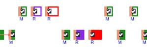
Figure 337 – Messages generated in parallel to data capture – Time View
Note: When specific messages from the actual network and from the Traffic Generator are received in parallel, they might be misinterpreted by the analyzer – i.e. a message from the system under test might be marked as a traffic generator message and vice versa. This situation might especially happen with short messages that cannot be differentiate - e.g. Beacon requests which do not include source address information, etc.
The user can choose to hide the Traffic Generated messages from the view by deselecting the relevant option from the Time View 'Show/Hide Elements' icon drop-down list (see par. IV.3.1):
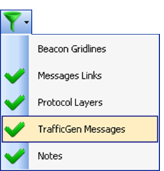
Figure 338 – Time View 'Show/Hide Elements' icon drop-down list
Note: When the 'TrafficGen Messages' option is deselected, the messages from the Traffic Generator application will also be removed from the Messages View tabs.