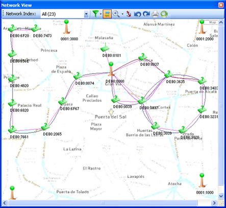
Network View devices can be displayed on top of a map or a floor plan and placed on a specific location set by the user:

Figure 168 – Network Topology on a Floor Plan
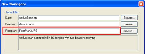
The floor plan or map image, in a .JPG format, can be defined in the New Workspace or Modify Workspace Settings forms (accessible through File/New and Tools/Workspace Settings respectively) or in the Capture form.

Figure 169 – Modifying a Floor Plan file
Devices can be manually moved (dragging their icon with the mouse) to their user preferred position over the floor plan.
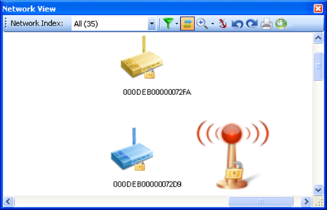
A device that has been manually moved will have the lock sign attached to its icon, to indicate a 'known position':

Figure 170 – Device with 'known' position in Network View
Devices' positions in the
floor plan are kept in the device file (.ANV). The export option in the Devices
View ( ) can be used for saving the device positions
over the floor plan for future use.
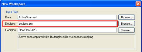
To load a predefined device position (and the other device related information contained in the device .ANV file), the device file should be defined in the New Workspace form or Data Capture, or in the capture forms, and can be later modified in the Workspace Settings menu:

Figure 171 – Loading a Device (.ANV) file